Summary
Most ship maintenance is still scheduled on fixed intervals: every so many running hours, every so many months. Fixed intervals are simple to plan and audit, but they rest on an assumption that is often wrong, namely that equipment wears out at a predictable age. Where that assumption fails, fixed-interval overhauls cost money, take machinery out of service, and can introduce faults through disturbance and reassembly.
Reliability-centred maintenance (RCM) and condition-based maintenance (CBM) replace the assumption with evidence. This paper explains the principles, shows how to decide which strategy fits which equipment, and sets out what a Planned Maintenance System (PMS) must hold for the strategy to work and to earn credit from class.
1. The problem with "age equals risk"
Fixed-interval maintenance makes sense when the probability of failure rises clearly with age or use. Some failure modes behave this way: wear of liners and rings, fatigue of components under cyclic load, erosion, ageing of elastomers. For these, a well-chosen interval removes the item before it reaches the steep part of its failure curve.
Many failure modes do not behave this way. The landmark study by Nowlan and Heap for United Airlines, published in 1978, analysed failure data across aircraft components and identified six distinct patterns of conditional failure probability against age. Only a minority showed a clear wear-out zone. Most components showed a constant or near-constant probability of failure after an initial period, and some showed elevated failure rates immediately after installation or overhaul ("infant mortality").
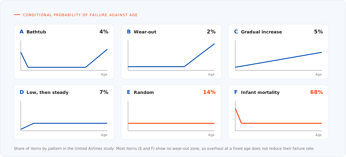
Figure 1. The six failure patterns. Source: Nowlan and Heap, Reliability-Centered Maintenance, United Airlines, 1978.
The practical consequences for a ship are significant:
- For equipment with a random failure pattern, overhauling at a fixed age does not reduce the probability of failure. It spends labour and spares, and may add early-life failures after reassembly.
- For equipment with infant mortality, intrusive maintenance can increase the failure rate.
- Effort is better spent detecting the onset of failure and acting just in time, or designing out the failure mode.
The study's findings came from aviation, but the same patterns are widely observed in rotating machinery, electrical equipment and electronics at sea. They are the starting point of modern maintenance strategy.
2. RCM decision logic
Reliability-centred maintenance is a structured process for deciding what maintenance each asset needs in its operating context. The SAE JA1011 standard (Evaluation Criteria for Reliability-Centered Maintenance Processes) defines what a process must do to be called RCM. In summary, it must answer seven questions for each asset:
- What are its functions and the associated performance standards in its present operating context?
- In what ways can it fail to fulfil those functions (functional failures)?
- What causes each functional failure (failure modes)?
- What happens when each failure occurs (failure effects)?
- In what way does each failure matter (failure consequences: hidden, safety and environmental, operational, or non-operational)?
- What should be done to predict or prevent each failure (proactive tasks and their intervals)?
- What should be done if no suitable proactive task can be found (default actions, such as failure-finding, redesign or run-to-failure)?
The key insight is that the consequence of failure, not the equipment itself, drives the decision. A pump whose failure stops the main engine needs a different strategy from an identical pump with a stand-by unit that starts automatically. The second pump's most important task may be a failure-finding test of the changeover, not an overhaul.
Task selection
RCM considers tasks in a preferred order, choosing the first that is both technically feasible and worth doing:
| Task type | Use when | Ship example |
|---|---|---|
| On-condition (CBM) | A detectable warning exists before functional failure, and the interval between warning and failure is long enough to act | Vibration trending on a purifier bowl bearing |
| Scheduled restoration or discard | Failure probability rises clearly with age, and most items survive to that age | Replacing elastomer seals at the maker's age limit |
| Failure-finding | The failure is hidden (it only shows when the protected function is demanded) | Testing high-temperature shutdowns, alarms and stand-by start |
| Redesign | No proactive task reduces the risk to an acceptable level and the consequence is safety or environmental | Adding redundancy or a different material |
| Run to failure | The consequence is purely economic and lower than the cost of prevention | Non-essential lighting fittings |
Hidden failures deserve special attention on ships. Protective devices, alarms, safety valves, emergency equipment and stand-by machinery often fail without any sign during normal operation. Their maintenance is failure-finding: periodic testing at an interval chosen so that the probability of the device being failed when needed stays acceptably low.
3. The P-F interval: making condition monitoring work
Condition-based maintenance depends on one concept: the P-F interval. Point P is the moment a developing failure first becomes detectable. Point F is functional failure. The time between them is the window in which the problem can be detected and corrected.
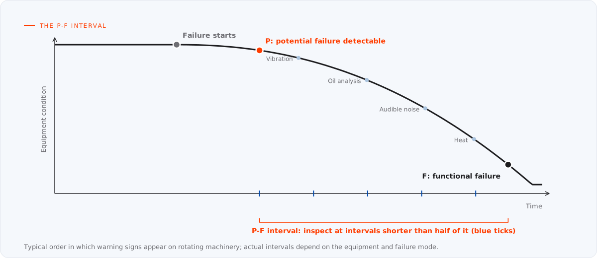
Figure 2. The P-F curve: more sensitive techniques detect failure earlier and widen the window for planned action.
Two rules follow:
- The inspection interval must be shorter than the P-F interval. A common rule of thumb is to inspect at half the P-F interval or less, so that at least one inspection falls inside the window with time left to plan the work.
- The technique determines P. More sensitive techniques detect failure earlier, widening the window. Vibration analysis typically detects bearing defects long before temperature rises or noise becomes audible.
| Technique | Typical failure modes detected | Notes |
|---|---|---|
| Vibration analysis | Bearing wear, imbalance, misalignment, looseness, gear defects | Broadband levels assessed against the ISO 20816 series; spectrum analysis for diagnosis |
| Lubricating oil analysis | Wear metals, contamination (water, fuel, coolant), oil degradation | Trend each machine against its own baseline, not only against fixed limits |
| Thermography | Electrical connections, switchboards, insulation, overheating bearings | Infrared inspection under load; ISO 18434-1 gives general procedures |
| Performance monitoring | Engine combustion, turbocharger fouling, heat exchanger fouling, pump wear | Cylinder pressure, exhaust temperatures, efficiency trends against shop test data |
| Ultrasound and acoustic emission | Leaks, early bearing defects, electrical discharge | Useful where vibration access is difficult |
| Visual and borescope inspection | Corrosion, cracking, deposits, wear patterns | Effective when combined with photo records in the PMS |
ISO 17359 (Condition monitoring and diagnostics of machines — General guidelines) provides a framework for setting up a monitoring programme: identify equipment and failure modes, select techniques, set alarm criteria, establish data acquisition, and define the actions that follow an alarm.
4. Choosing equipment for CBM
CBM is not appropriate everywhere. It is worth implementing where all of the following hold:
- The failure has significant consequences: safety, environmental, off-hire, or high repair cost.
- A reliable, measurable indicator of the developing failure exists.
- The P-F interval is long enough to detect the problem and plan the work.
- The cost of monitoring is lower than the cost of the failures and fixed-interval work it replaces.
On most merchant ships this points to main and auxiliary engines, turbochargers, main and essential pumps, purifiers, compressors, propulsion shafting and stern tube, steering gear, main switchboards and large electric motors. For low-consequence equipment, fixed intervals or run-to-failure usually remain the economic choice.
5. Class: getting credit for CBM
Classification societies recognise that well-run condition monitoring can be more effective than fixed-interval opening up. Several societies publish rules or guides that allow survey credit for machinery under an approved condition monitoring or reliability-based maintenance programme. Examples include the ABS Guide for Surveys Based on Machinery Reliability and Maintenance Techniques and DNV's machinery condition monitoring arrangements. The details differ between societies, and the society's current rules are the reference.
Typical elements a society expects include:
- an approved planned maintenance arrangement as the foundation;
- a defined list of machinery under the programme, with the techniques and intervals for each;
- baseline measurements, normally taken when the machinery is new or after overhaul;
- alarm and action limits, and documented actions when limits are exceeded;
- qualified personnel or approved service suppliers for measurement and analysis;
- records retained and available to the surveyor, with periodic review.
When credit is granted, items that would otherwise be opened up for survey may be accepted on the basis of satisfactory condition data. The data quality in the PMS is what makes that possible.
6. What the PMS must hold
CBM fails in many fleets not because the technique is wrong but because the data cannot be found, trended or acted on. A PMS that supports CBM needs:
- Measurement points defined per equipment, with the parameter, unit, technique and location (for example, "purifier vertical bearing, velocity mm/s RMS").
- Baselines and limits stored against each point, including the source of the limit (maker, ISO guideline or fleet experience).
- Readings recorded as data, not text. A number in a structured field can be trended; a sentence in a remarks box cannot.
- Triggered work orders. When a reading crosses an action limit, the PMS should raise or bring forward a corrective job, with the reading attached.
- Failure records with cause codes. When equipment fails or is found defective, record the failure mode and cause in coded form. This is the evidence that later justifies changing intervals or strategies.
- Links to external reports. Oil analysis and vibration reports from laboratories and service providers should be attached to the equipment, not lost in email.
Paper 05 in this series, on equipment hierarchies and master data, describes how to structure these records so they can be compared across a fleet.
7. A practical roadmap
A fleet does not need to convert every system at once. A staged approach works better:
- Clean the foundation. Verify the equipment register and job library against the makers' documentation (see paper 01).
- Rank criticality. Classify equipment by the consequence of failure, starting with ISM Code critical equipment.
- Analyse the top tier. Apply RCM logic to the highest-consequence systems first. Identify hidden failures and set failure-finding tests.
- Introduce monitoring where it pays. Start with vibration and oil analysis on critical rotating machinery and engines; establish baselines.
- Record failures properly. Introduce failure and cause coding in the PMS so the programme can learn.
- Review and adjust. At least annually, review failures, alarms and findings; adjust intervals and tasks through management of change.
- Approach class. When data and procedures are mature, apply for the society's condition monitoring or reliability-based arrangement.
Conclusion
Fixed intervals are a reasonable default but a poor end state. Reliability-centred maintenance asks what each failure costs and what can realistically prevent it; condition-based maintenance acts on evidence instead of age. Both depend on a PMS that holds clean equipment data, structured measurements and honest failure records. Fleets that build that foundation gain fewer surprises, lower maintenance costs and, with class approval, credit for the work they already do.
References and further reading
- F. Stanley Nowlan and Howard F. Heap, Reliability-Centered Maintenance, United Airlines for the US Department of Defense, 1978.
- SAE International, JA1011: Evaluation Criteria for Reliability-Centered Maintenance (RCM) Processes.
- ISO 17359, Condition monitoring and diagnostics of machines — General guidelines.
- ISO 20816 series, Mechanical vibration — Measurement and evaluation of machine vibration.
- ISO 18434-1, Condition monitoring and diagnostics of machines — Thermography — Part 1: General procedures.
- International Maritime Organization, International Safety Management (ISM) Code, section 10.
- ABS, Guide for Surveys Based on Machinery Reliability and Maintenance Techniques; the rules of the vessel's own classification society.
- Companion papers: From instruction book to job library and Running hours, calendar intervals and class.
Planning a move to condition-based maintenance? We structure PMS data, measurement points and failure coding so that condition monitoring can be trended and credited. See our Planned Maintenance System services.